Soil Moisture sensor with Arduino in Tinkercad | how to use soil moisture sensor in Tinkercad Circuit diagram: Arduino Sketch: // C++ code // int moisture_data = 0; void setup() { pinMode(A0, INPUT); Serial.begin(9600); pinMode(12, OUTPUT); pinMode(6, OUTPUT); } void loop() { moisture_data = analogRead(A0); Serial.println(moisture_data); if (moisture_data < 21) { digitalWrite(12, HIGH); digitalWrite(6, HIGH); } else { digitalWrite(12, LOW); digitalWrite(6, LOW); } delay(10); // Delay a little bit to improve simulation performance }
Interfacing Seven
segment display with Arduino
In this project, we will interface seven segment display
with an Arduino
For various application in day-to-day life, we need
display to show the values and much more things, and there is no point to use
expensive OLED and LCDs available in the market. Then what is the solution for
this so we are having less expensive display and that is a simple seven-segment
display. It is mainly use to display the numbers and some alphabets. Seven
segment display has 7 LEDs which are arranged in the shape of 8. See the image
below.

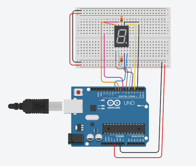
Circuit Diagram:
Components Required:
§ Arduino
UNO
§ Seven
Segment Display
§ Resistors
-02
§ Connecting
wires
Connection:
The hardware a part of this project
looks quite messy but if we go step by step its simple and easy to place
together. First of all, we make the connections for the 7-segment display with
the Arduino. The connections for 7-segments with the Arduino given in the above
circuit diagram and below table.
7 segment display has 5 pins on
upper side and 5 pins on downside.
Total 7-segment that is a,b,c,d,e,f,g see the picture below

Types
of 7-segment display: there are two types of display available in market that
is common anode and common cathode. In this tutorial we are using the common
anode type of display.
There is bit difference
in both the displays as their name suggest that the common cathode type of
display has all the cathodes of the 7-segments connected at one place. And same
for the common anode type of display the anodes of the 7-segments connected at
one place.
1. The Common Cathode
displays.
In the common cathode type of display, all the cathode connects together to logic “0” or GND. The individual segments are turned on using “HIGH”, or logic “1”.
The Common Anode displays
In the common anode
type of display, all the anode terminals connected together to logic “1”. The
individual segments are turned on using the, logic “0” or “LOW” digital signal.
Connection:
In this tutorial we are using common
anode type of display.
|
Seven segment pins |
Arduino pins |
Wire Color |
|
A |
2 |
Black |
|
B |
3
|
Yellow |
|
C |
4 |
Purple |
|
D |
5 |
Turquoise |
|
E |
6 |
Brown |
|
F |
7 |
Pink |
|
G |
8 |
Orange |
|
Dp |
9 |
blue |
|
Common pin 3 & 8 |
+5V |
Connected using resistor |
Pin no 3 & 8 connected to the +5V through resistor.
For displaying the numbers coding explanation.

Case 1: to display “0”
For displaying 1 on
the 7-segment display we need to turn on following segments
Ø
a,b,c,d,e,f segment “g” turned off

As we are using the
common anode type of display, to turn on each segment we need to make the
digital pins low or logic “0”
Case 2: to display “1”
For displaying 0 on
the 7-segment display we need to turn on following segments
Ø
segment b,c turn on and other segment
turn off a,d,e,f,g

As we are using the
common anode type of display, to turn on each segment we need to make the digital
pins low or logic “0” b and c is connected to the 3 & 4 respectively make
it low to turn on.
Case 3: To display “2”
For displaying 2 on
the 7-segment display we need to turn on following segments
Ø
segment a,b,g,e,d turn on and other
segment turn off c,f

As we are using the
common anode type of display, to turn on each segment we need to make the
digital pins low or logic “0” pins a,b,g,e,d is connected to the 2,3,8,6,5
respectively make it low to turn on and give the delay of 1 sec.
Case 4: to display “3”
For displaying 3 on
the 7-segment display we need to turn on following segments
Ø
segment a,b,g,c,d turn on and other
segment turn off e,f

As we are using the
common anode type of display, to turn on each segment we need to make the
digital pins low or logic “0” pins a,b,g,c,d is connected to the 2,3,8,4,5
respectively make it low to turn on and give the delay of 1 sec.
Case 5: to display “4”
For displaying 4 on
the 7-segment display we need to turn on following segments
Ø
segment f,g,b,c turn on and other
segment turn off a,e,d

As we are using the
common anode type of display, to turn on each segment we need to make the
digital pins low or logic “0” pins f,g,b,c is connected to the 7,8,3,4
respectively make it low to turn on and give the delay of 1 sec.
Case 6: To display “5”
For displaying 5 on
the 7-segment display we need to turn on following segments
Ø
segment a,f,g,c,d turn on and other
segment turn off b,e

As we are using the
common anode type of display, to turn on each segment we need to make the
digital pins low or logic “0” pins a,f,g,c,d is connected to the 2,7,8,4,5
respectively make it low to turn on and give the delay of 1 sec.
Case 7: To display “6”
For displaying 6 on
the 7-segment display we need to turn on following segments
Ø
segment a,f,g,e,c,d turn on and other
segment turn off b

As we are using the
common anode type of display, to turn on each segment we need to make the
digital pins low or logic “0” pins a,f,g,e,c,d is connected to the 2,7,8,4,6,5
respectively make it low to turn on and give the delay of 1 sec.
Case 8: To display “7”
For displaying 7 on
the 7-segment display we need to turn on following segments
Ø
segment a,b,c turn on and other segment
turn off d,e,f,g

As we are using the
common anode type of display, to turn on each segment we need to make the
digital pins low or logic “0” pins a,b,c is connected to the 2,3,4 respectively
make it low to turn on and give the delay of 1 sec.
Case 9: To display “8”
For displaying 8 on
the 7-segment display we need to turn on following segments
Ø
segment a,b,c,d,ef,g, turn on

As we are using the
common anode type of display, to turn on each segment we need to make the
digital pins low or logic “0” pins a,b,c ,d,e,f is connected to the 2,3,4,5,6,7,8
respectively make it low to turn on and give the delay of 1 sec.
Case 10: To display “9”
For displaying 9 on
the 7-segment display we need to turn on following segments
Ø
segment a,b,g,f,c,d turn on and e
should turn off

Watch the Working Video:
Arduino Sketch:
void setup()
{
pinMode(2, OUTPUT);
pinMode(3, OUTPUT);
pinMode(4, OUTPUT);
pinMode(5, OUTPUT);
pinMode(6, OUTPUT);
pinMode(7, OUTPUT);
pinMode(8, OUTPUT);
pinMode(9, OUTPUT);
}
void loop()
{
digitalWrite(2, LOW);
digitalWrite(3, LOW);
digitalWrite(4, LOW);
digitalWrite(5, LOW);
digitalWrite(6, LOW);
digitalWrite(7, LOW);
digitalWrite(8, HIGH);
delay(1000); // Wait for 1000 millisecond(s)
digitalWrite(2, HIGH);
digitalWrite(3, LOW);
digitalWrite(4, LOW);
digitalWrite(5, HIGH);
digitalWrite(6, HIGH);
digitalWrite(7, HIGH);
digitalWrite(8, HIGH);
delay(1000); // Wait for 1000 millisecond(s)
digitalWrite(2, LOW);
digitalWrite(3, LOW);
digitalWrite(4, HIGH);
digitalWrite(5, LOW);
digitalWrite(6, LOW);
digitalWrite(7, HIGH);
digitalWrite(8, LOW);
delay(1000); // Wait for 1000 millisecond(s)
digitalWrite(2, LOW);
digitalWrite(3, LOW);
digitalWrite(4, LOW);
digitalWrite(5, LOW);
digitalWrite(6, HIGH);
digitalWrite(7, HIGH);
digitalWrite(8, LOW);
delay(1000); // Wait for 1000 millisecond(s)
digitalWrite(2, HIGH);
digitalWrite(3, LOW);
digitalWrite(4, LOW);
digitalWrite(5, HIGH);
digitalWrite(6, HIGH);
digitalWrite(7, LOW);
digitalWrite(8, LOW);
delay(1000); // Wait for 1000 millisecond(s)
digitalWrite(2, LOW);
digitalWrite(3, HIGH);
digitalWrite(4, LOW);
digitalWrite(5, LOW);
digitalWrite(6, HIGH);
digitalWrite(7, LOW);
digitalWrite(8, LOW);
delay(1000); // Wait for 1000 millisecond(s)
digitalWrite(2, LOW);
digitalWrite(3, HIGH);
digitalWrite(4, LOW);
digitalWrite(5, LOW);
digitalWrite(6, LOW);
digitalWrite(7, LOW);
digitalWrite(8, LOW);
delay(1000); // Wait for 1000 millisecond(s)
digitalWrite(2, LOW);
digitalWrite(3, LOW);
digitalWrite(4, LOW);
digitalWrite(5, HIGH);
digitalWrite(6, HIGH);
digitalWrite(7, HIGH);
digitalWrite(8, HIGH);
delay(1000); // Wait for 1000 millisecond(s)
digitalWrite(2, LOW);
digitalWrite(3, LOW);
digitalWrite(4, LOW);
digitalWrite(5, LOW);
digitalWrite(6, LOW);
digitalWrite(7, LOW);
digitalWrite(8, LOW);
delay(1000); // Wait for 1000 millisecond(s)
digitalWrite(2, LOW);
digitalWrite(3, LOW);
digitalWrite(4, LOW);
digitalWrite(5, LOW);
digitalWrite(6, HIGH);
digitalWrite(7, LOW);
digitalWrite(8, LOW);
digitalWrite(9, LOW);
delay(1000); // Wait for 1000 millisecond(s)
}
Like share and comment :


Comments
Post a Comment
If you any query please comment