LED brightness control
using Arduino and potentiometer.
In this
tutorial, we are controlling the LED brightness using the potentiometer. This is
an easy tutorial for demonstrating how can we control the brightness of an LED
or adjust the speed of a DC motor using Arduino Board, and potentiometer. in
this tutorial we have used the three LEDs yellow, blue, green to control the
brightness of the same.
Circuit Diagram:
Components Required:
§ Arduino
UNO
§ Yellow
LED
§ Blue LED
§ Green LED
§ Potentiometer
10K
§ Connecting
wires
Connection:
The
hardware part of this project is very simple and easy to place together. First
of all, make the connections for LEDs with the Arduino.
Connect
the anode of the yellow LED to the digital pin12 of an Arduino.
Connect
the anode of the Blue LED to the digital pin 8 of an Arduino.
Connect
the anode of the Green LED to the digital pin 4 of an Arduino.
Connect
the cathode pin of all LEDs to the GND pin of an Arduino.
Let’s
do the connection for the potentiometer now,
Connect
the terminal-1 of the potentiometer to the GND of an Arduino.
Connect
the terminal-2 of the potentiometer to the +5V of an Arduino.
Connect
the middle terminal of the potentiometer to the analog input A0 of an Arduino.
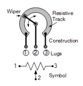
What is a Potentiometer?
A potentiometer (also called the pot) it’s a 3 terminal variable
resistor in which the resistance is manually controlled or varied by rotating
the nob clockwise or anticlockwise. Thus by varying resistance, we can able to produce
the changing voltage output.
Applications of Potentiometer:
following are the practical application of the potentiometer.
- The pot
is used as a voltage divider in many electronic circuitries.
- The potentiometer is used in radio, television, and media
players for volume control
- Potentiometers are widely used in sound
controls in various amplifiers.
Working on the project:
As per the circuit diagram, the output
voltage of the potentiometer is connected to the analog input pin A0 of an Arduino.
The potentiometer gives the Analog output when it is rotated. The output of the potentiometer
is stored in a variable named inputval.
Three LEDs are connected to the digital pin 12,8,4 respectively.
Whenever the pot rotated clockwise the output voltage increases
thus the brightness of all three LEDs also increases.
Whenever the pot rotated anticlockwise the output voltage
decreases thus the brightness of all three LEDs also decreases.
Arduino
Code Explanation:
Define
the LED and pot pin led1 is connected to pin 12, led2 is connected to pin 8, led3 is connected to pin 4, and the pot is connected to the analog input A0.
Declare the variable name inputval and set it to “0”
int led1=12;
int led2=8;
int led3=4;
int pot=A0;
int inputval=0;
Inside the
void setup, we will define the pin which are input and which are output pins,
this set of code runs only once.
void setup()
{
pinMode(led1,OUTPUT);
pinMode(led2,OUTPUT);
pinMode(led3,OUTPUT);
pinMode(pot,INPUT);
}
the code
inside the void loop runs over and over as long as the Arduino Board is turned
on.
Here
inside the loop store the pot value in the variable named potval.
void loop()
{
inputval=analogRead(pot);
analogWrite(led1,inputval);
analogWrite(led2,inputval);
analogWrite(led3,inputval);
delay (100);
}
Here we have to use the analogWrite function for all 3 LEDs to
control the brightness.
Watch Working Video:
Thanks for subscribing to my Youtube channel, here is the good news for you!! now you can join my Udemy course for FREE. fill the below form and you will receive the free Udemy coupon code in your mail. Click on the below link.
https://docs.google.com/forms/d/e/1FAIpQLSfY7sanjTlF6qgfFOo5mY68J8izOklnZ_f5-fJ3ecuQFsImmw/viewform?usp=sf_link
Arduino Sketch:
int led1=12;
int led2=8;
int led3=4;
int pot=A0;
int inputval=0;
void setup()
{
pinMode(led1,OUTPUT);
pinMode(led2,OUTPUT);
pinMode(led3,OUTPUT);
pinMode(pot,INPUT);
}
void loop()
{
inputval=analogRead(pot);
analogWrite(led1,inputval);
analogWrite(led2,inputval);
analogWrite(led3,inputval);
delay (100);
}


Comments
Post a Comment
If you any query please comment